Assembly Instructions
Overview
This page has the general assembly instructions for all the MetroM devices. The instructions will be roughly the same for all the devices.
Preparation
Prerequisites
You need to be old enough to operate a pair of scissors.
Required Tools
- Scissors
- The Parts in the Parts List
- This instruction manual
Recommended Tools
-
Paperclip
Or something sharp for removing bits of stuck wood -
Screwdriver
Not necessary since thumb nuts are provided
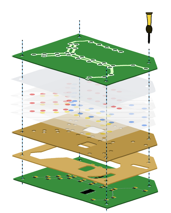
Layers
| Layer | Count | Image |
|---|---|---|
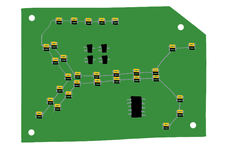
|
Design Layer The PCB Layer that looks pretty but isn't functional |
1 | |
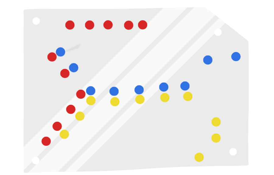
|
Colour Filter Sheets of printed transparency plastic to give the lights colour. This layer is optional if you like having white lights. |
3 | |
|
Diffuser A piece of vellum (tracing paper) to diffuse the lights and make it less piercing to look at. |
1 | |
|
Light Insert A sheet of wood that helps direct the light and reduce light leakage from the sides. |
1 | |
|
Electronics Guard A sheet of wood that protects the delicate electronics from being damaged by the layers above it. |
1 | |
|
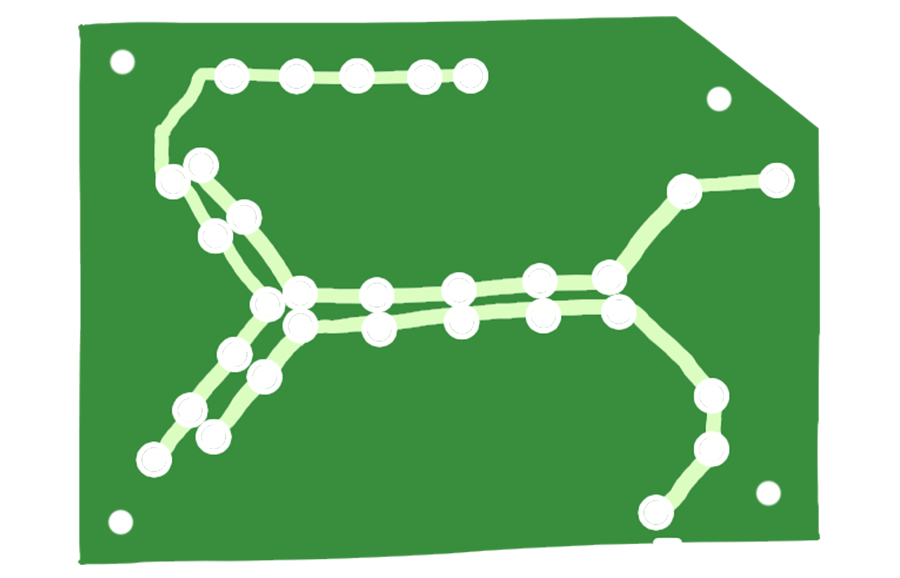
Lighting Layer The PCB that contains all the electronics, lights, and buttons |
1 |


Best Practices
Always check the direction of the componets before soldering it. If you have mistakenly soldered an IC upside down, it is very difficult to remove and redo it. In the event that happens, you will likely need a solder wick and a lot of patience.
For soldering any component, it’s best to solder only one pin first and then check if it’s aligned. If it’s not aligned, you will be able to melt the solder and reposition the component/ After that, solder the second pin that’s diagonally across. By doing this, you can be sure that the component is positioned correctly before soldering the rest of the pins.
For all components, you can choose to use Male to Female header pins instead of soldering them directly to the board. This means that you can easily remove and replace components if necessary.
Assembly
Step 0 - Test Board
Plug the board into a USB power supply and turn it on.
The board likely will have come partly assembled. Just without the colour filters. When you turn it on, some of the lights might look broken, but that's because the electronics guard might have bits stuck in them.
Step 1 - Prepare the Inserts
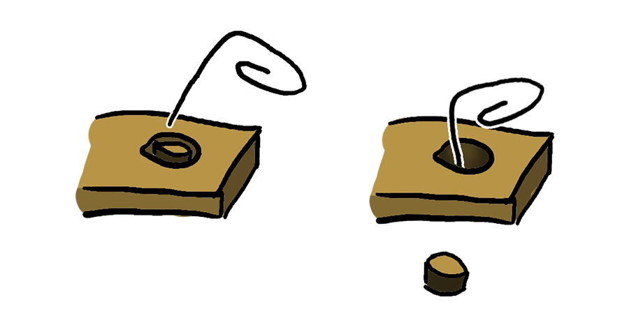
Take apart the board and inspect the inserts, every hole should be unblocked.
Sometimes there will be pieces of wood still stuck in the holes due to the manufacturing process. All you need to do is to use something sharp like a paperclip to clear the holes.
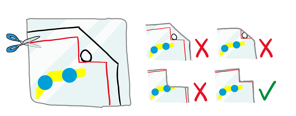
Step 2 - Cut Out the Colour Filters
The colour filters need to be cut out along the red line.
For the most part, you don't have to be very careful along the borders as long as you don't cut away any of the coloured dots.
Be extra careful around the corners where the screw holes are. Since if you don't cut it out properly, the filters won't align and the colour would not look as nice as it should.
Step 3 - Assemble the Sandwich
Now that you have all the parts ready, you can put it all together.
The colour filters won't hold by themselves and will easily fall out, it's easier to assemble the thing upside down.
The screws should also not require a screwdriver as the nuts can be screwed in with your thumb.
Step 4 - Enjoy
That's it. If you have any questions, please don't hesitate to contact me at hello at lifeclo.cc
Troubleshooting
Lighting
Some lights are not working
Check if the lights are being blocked by any of the layers. If the LED itself is broken, please contact me and I'll help you with a replacement.
Programming
This was made to be reprogrammable, you can find the instructions on how to program it on the github page.